

Workbench Review – QRP Labs QCX+ Kit
 Earlier this year Ian M0IDR reviewed the original QCX kit from QRP Labs. Now it’s been redesigned as the QCX+, which Chris G3YHF reviews here.
I have added comments from Hans G0UPL of QRPLabs to my original post – these are in italics.
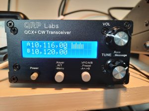
QRP Labs have recently started shipping the new QCX+, a single band CW/WSPR transceiver kit. Mine arrived carefully packed along with the additional metal enclosure.
Although the QCX+ as delivered is CW only, the original QCX has been modified by experimenters to enable SSB and digital modes. The QCX+ is likewise a rig designed for modification – with lots of spare pin headers and a separate development board.
I built the 30m version, pictured above.
There is an impressive downloadable manual running to almost 200 pages, covering the build, alignment, operating features, fault finding, facilities for experimenting and more!
The build instructions are very detailed and easy to follow, with a large diagram illustrating each step. The proof is that my rig worked first time!! That was a relief!
I initially checked and sorted all the components, putting them in labelled envelopes to make them easier to find. 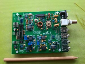
The trickiest part – winding the four section RX transformer (centre top of picture) – is the first task and gets this job out of the way. Then each type of component is installed in turn.
The silk-screen printed PCB is a delight to work on. My trusty 25 watt Antex iron was just right for soldering the components to the 2 PCBs. Although there is more room on these PCBs than on the original QCX, a small tip is required to keep the solder points neat and avoid problems.
Thanks to Ian M0IDR for advice on this, as the QCX+ was the most complex build I have attempted.
The manual emphasises that the enamelling on the wire used for toroid windings needs to be burnt off during soldering, and that failure to achieve this is the most common reason for a QCX build to be unsuccessful first time. This requires the soldering iron to be applied longer than normal. Continuity testing for zero ohms across the winding is recommended. I had a couple of instances where I needed to resolder to completely burn off the enamelling.
In fact, I continuity tested each component before triming any loose wires. I find my analogue multimeter is better to use for this than a digital one, as the needle flicking right across the scale clearly indicates a good connection.
Alignment is simple process using the rig’s inbuilt test equipment, which includes a signal generator.
 I had two small self-inflicted problems in the build.
I discovered that I had soldered the ends of one of the RX transformer windings the wrong way round, having already trimmed off the wire. Luckily, I also found that I had wound one too many turns. I managed to unwind the extra turn without having to desolder the other 6 connections on this toroid, and then had enough spare wire to solder this winding back on to the PCB. Phew!
This error arose because I wanted to finish installing the transformer even though it was late in the evening. The moral is: stop before you get tired!
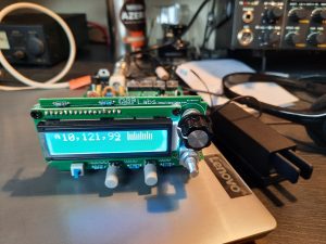
The second problem was that when I switched the rig on, the LCD lit up but didn’t show the initial ‘choose band’ screen. A quick check and I discovered I’d omitted to install the microcontroller into its socket.
The rig in test mode is shown above, before fitting in to the enclosure. This is a sturdy 4mm/2mm thick with laser etched lettering. The 2 PCBs – one holding the LCD – join at right angles and slide easily into the enclosure.
It’s easy to remove the top of the enclosure or slide the PCBs out to make mods to the rig.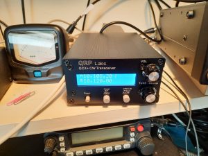
The rig is easy and intuitive to use. As a 99% CW op, I was impressed at how clear the CW signals were in such a small rig. The 200hz filter must help in this regard, and although it’s a sharp filter there is no ringing.
With masses of audio gain available, and no RF control, I found winding the ‘VOL’ control back helped bring any weak signals out of the noise. There is full QSK, although this can be switched off.
Tuning rates are 1kHz, 500Hz, 100Hz and 10Hz – selected by depressing the tuning knob. This scrolls in a loop – so from 10Hz it goes round to 1kHz. A long hold on the tuning knob is supposed to enable the cursor to move to the left, i.e. from 10Hz to 50Hz. However I found it difficult to avoid starting my stored CQ message, which is also activated by depressing the same knob.
Hans G0UPL: Have a look at menu “7.1 Dbl. click” which defaults to 300 milliseconds; this is the length of time that you must hold a button, in order for it to be recognized as a long press. If you are having difficulty making the SHORT press that is necessary to move the cursor, then you can increase this value beyond 300 milliseconds, so that the threshold for identifying it as a LONG press, is slower.
Keyer speed and RIT are available with one and two presses of a button. There are twin VFOs and memory functions, as well as a message facility and CW decoder. Many other functions are available and adjustable.
There are sockets to enable CAT control and to connect an external GPS RX to the rig’s GPS interface.
 The rig is specified to deliver up to 5 watts depending on supply voltage. Using a 13.5v PSU, my QRP power meter read 3.5 watts out (normal power meters don’t give accurate readings at QRP levels). As I don’t have a variable power supply, I tried the rig connected to a SLAB measuring 12.3v and it delivered 2.75 watts out.
According to the data sheets in the manual, it should deliver 4 watts at 13.5 volts. The manual – and discussion on the QCX forum – advise taking a turn off each of the low pass filter torroids in case the cut-off frequency is too low.
Hans G0UPL: About power output… since writing the manual, there have been improvements to the technique of optimizing power output. It is not merely a matter of lowering inductance so as to increase the cut-off frequency. It is also necessary to match to the Class-E PA output impedance which is evidently not precisely 50-ohms. This is a process of trial and error as it can be different in each case. I recorded a YouTube video on this topic, see https://youtu.be/
Overall, I’m delighted with successfully building this kit and with it’s performance on air. My first 3 qsos received reports of 549 from Italy and 559 from Germany (another QRP op) – both in response to my CQs – and 569 from Norway. Later in the evening I worked east coast USA, receiving 559. I heard a VK, although only S3. The RBN for my CQ calls gave very good SNR reports. The antenna was a dipole at about 25 feet.
So I’m looking forward to having some fun on 30 meters with this QRP rig!
The kit is suitable for someone who has undertaken some basic constructional projects, can solder effectively and wants to move on to something more complicated. It certainly left me feeling much more confident about tackling an advanced project.