

How to operate 160 – 10M from a small garden
Don’t let a small garden stop you from getting on HF – including 160M! – reports Wythall Radio Club member Chris G0EYO.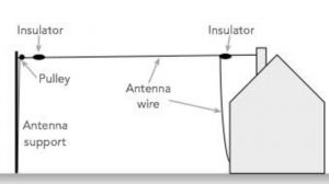
End Fed (or long wire) antennas are the most simple antennas an amateur can make for the HF bands. However their simplicity does come with serious compromises when used as a multi-band antenna.
The physical length as measured in wavelengths of the transmitting frequency can result in very high or very low complex impedances at the fed end of the wire, so they need a very good antenna matching unit (AMU) to enable a good match to the transceiver and to deal with the high voltages or current that may exist,
The high currents or voltages at the end of the wire can also result in serious RFI problems for the amateur which are hard to control. This is because a quarter-wavelength in from the far end of an end fed antenna, the current is at maximum and the voltage is at minimum. At a half-wavelength the reverse occurs and so on.
So for a given length of wire and depending upon the band being used a wide range of complex impedances and currents and voltages may appear at the transmitter end of the wire. This is sometimes more than the AMU can handle, both in terms of impedance matching and voltages.
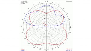 The end fed wire antenna produces quite complex radiation multi-lobe patterns unlike the simple “figure of eight” radiation pattern produced by a dipole. With multi-lobes come deep nulls in certain directions (diagram thanks to VK6YSF).
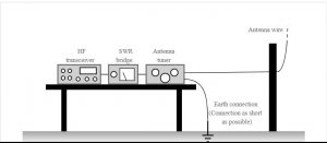
They also need a counterpoise or earth return to work well and avoid RF getting back into the shack. Ideally these should be about a quarter-wavelength long for each band the antenna is required to be used on.
We can avoid some of these issues if we can avoid wire lengths which are multiples of a quarter-wavelength of the bands being used.
So how long should our end fed wire be? A great deal of work has been done by others on the ideal wire length which avoids very large end impedances for the bands of interest and these can be found courtesy of Google.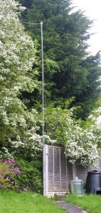
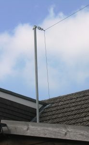
My garden allowed an end fed wire length of approximately 25m to be accommodated in an inverted “L” format between a 10ft pole mounted on the side of the garage and a 20ft pole mounted at the bottom of the garden.
Alan Chester G3CCB in his book “ HF Antennas for Everyone” (RSGB) came up with a useful graphic which showed “practical” lengths for end fed wires. This allows you to pick a length and see which bands are will give you a matchable end impedance.
 I wanted to work on all bands from 160m to 10m but ideally 80m, 40, 20m 15m and 10m. Alan’s calculations showed that a wire length of 18.5m would give an workable end impedance on 80m, 30m, 20m, 17m, 15m and 10m with possibly a little more troublesome end impedance on 160m, 40m, and 12m.
To avoid bringing high voltages and currents into the shack the AMU should be mounted outside and the signal fed into the shack via 50 ohms coax. Fortunately I had an SGC 230 Auto AMU that I had installed at my previous house in Hollywood.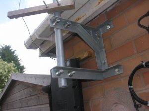
The SGC 230 AMU is designed to operate with wire antennas and is configured as an “L” or “Pi” type network controlled by a microprocessor. The initial tuning takes several seconds to determine the transmit frequency and then select the necessary coils and capacitance to match the complex impedance of end fed wire to 50 ohms. These settings are stored in a non-volatile memory so the subsequent retuning of the same antenna on the same frequency only takes a fraction of a second.
The tuner has a ceramic insulated antenna terminal which looks as if it would tolerate quite a few volts, and a threaded nut for a earth counterpoise. It has a flying lead from the AMU with a 50 ohm coax and PL259 connector for the transceiver together with a 5 core cable for +12V DC, earth and “Lock Tune” control line and “Remote Tuner” indicator line.
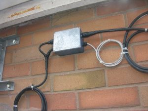 On my installation I have a small plastic box next to the AMU which is a through line for the coax cable and a terminal block for the DC and control lines. A 25m length of RG213 goes from the interconnecting box back to the shack in a bedroom at the front of the bungalow. Similarly a CAT5 cable is used to feed the DC and control lines back to a remote indicator and switch box at the operating position. This tells me when the SG230 has achieved a satisfactory match and locked on (and which can be confirmed by the SWR meter).
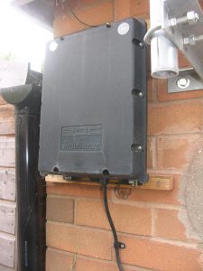
The SGC230 AMU is in a weather proof plastic box and is mounted under the eaves of my garage. A very short earth counterpoise is connected to the AMU earth terminal using copper braid and fixed to a 1 m earth rod driven into the ground. Overall the earth counterpoise is about 5m long and should probably be longer or with multiple earth rods. Chris G3YHF has suggested I do this modification to see if the efficiency improves. The antenna wire itself is Kevlar strengthened wire which is very strong but also very thin.
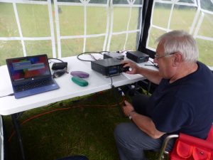
The pictures show the installation. I should say at this point that the inspiration to put in this antenna came entirely from Roger M0GWM who in 2019 said it was about time I put up some antennas having lived here for 3 years. Together we came up with the idea of using a long wire. Roger also did all of the installation work including running the coax and control cables around the bungalow just under the eaves.
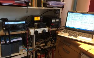 Not long after the installation was completed, and always being a data mode fan, I got Ian M0LQY to set up FT8 on my computer and transceiver which is controlled by an old version of Ham Radio Deluxe. I limit the power to 30W (effectively carrier power – and probably equivalent to 100W PEP for SSB) and have been very pleased with the results.
Bands 160m, 40m, 20m, 17m 15m and 10m are rock solid. 30m suffers from RFI which upsets the wired mouse on the main PC in the shack and 30m seems to be constantly trying to find a good match. SWR’s achieved on these bands are between 1.15:1 and 1.35:1 which I am very happy with.
Strangely enough I never tried top band on any mode until Chris G3YHF encouraged me to do so on FT8. I found it fun and challenging so made it my Wythall Radio Club DXCC challenge for 2020 (55 countries on 160M at time of writing). Chris has a similar set up with slightly longer wire length and bigger earth counterpoise. Analysis of PSK Reporter reports shows he just has the edge on me when it comes to performance, so don’t let a small garden stop you working 160M – 10M!
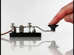
 At Wythall Radio Club during May we celebrate the skill of communicating by Morse Code in honour of Lew Williams, who was an expert at Morse and former Club President.
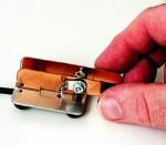
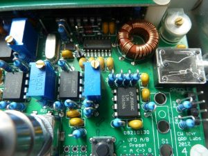 The multi-winding coil was by far the most difficult to assemble but inductance measurements proved each winding before fixing into position (photo left).
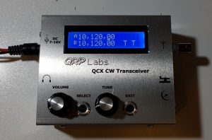
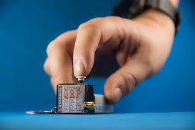
 This module is only available in kit form and interfaces to the QCX via a 4 core umbilical cord.
 In addition there will be one practical assessment session, usually on a Saturday, where you will learn soldering, digital measuring and other skills. This will require you to be available for ONE Saturday in April, but there will be a choice of dates.
 The course is FREE but there will be an exam fee of £32.50, an exam room hire fee of £6 and a project kit and materials fee for the practicals of £12. You will not need to pay this until the course starts.
 Radio signals from Wythall Radio Club members reached remote parts of the world – including New Zealand, Sri Lanka, Mali, Seychelles, Guinea-Bissau, British Virgin Island and South Korea.
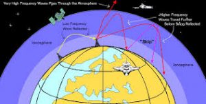
 John M6KET won the Foundation licence category with 78 countries contacted, using QRP (low power) – no more than 10 watts output and a simple wire antenna.
 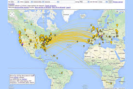 It shows what can be achieved with simple equipment despite the poor radio conditions.
 Chris G0EYO won the ‘midnight oil’ award for contacting 50 countries on Top Band (160 meters), again using low power and a simple wire antenna. The award is called ‘midnight oil’ because Top Band contacts can normally only be made during nightime, due to propogation conditions.
 As December is ‘
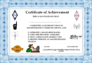
 The specially designed course provides you with an exciting introduction to the hobby. After passing the straight-forward multiple choice exam, you can obtain your own callsign for use when communicating with other radio amateur operators worldwide.
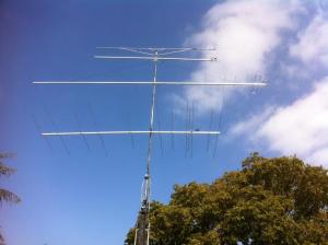
 We will set a date for the practical assessments (usually done as a group on a Saturday) and the exam when we know how many people will be on the course. These should be done in January or early February.
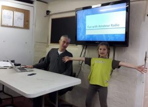
 Having gained some knowledge and experience, the evening concluded with the Brownies sending greetings messages by VHF radio to Jan M3YXM, another Club member operating from her home.