

THE SEARCH FOR AN ACCURATE FREQUENCY STANDARD INPUT by DAVID G7IBO
198KHz GONE!
WHAT DO WE DO NOW??
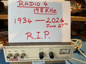
Radio 4 198KHz ceased transmission on 27th June 2026 after 92 years on the air. No great loss you may think as most listeners have many other options to tune into the ‘Archers’ etc. It is a great loss to many electronic hobbyists.
The highly accurate 198KHz transmission frequency was used by equipment such as the Quartzlock model 2A (shown below right) to provide a frequency standard for use in electronic equipment. The loss of the Radio 4 signal has made all such pieces of equipment redundant.
Until recently there were few other solutions open to electronics enthusiasts. The Rubidium Standard machines were extremely expensive even on the 2nd hand market (and have limited life). However, with the advent of cheap devices using GPS technology the ability to provide accurate frequency standards has become more readily available.
I have one of the above mentioned Quartzlock devices and with its demise I looked for a solution which would provide the same (or better). The Quartzlock provided square waves of 10MHz, 5MHz, and 1MHz all of which I had used to enhance the accuracy of test equipment in my shack. In anticipation of the loss of 198KHz I had purchased a Geostationary Positioned Satellite disciplined oscillator (GPSDO). I found a BH3SAP device for around £60. Inevitably these have increased in price by at least 50% as they have become more useful. This particular device is sold on various platforms and is open source. There have been a number of contributors to alternative firmware and it is now a very capable piece.
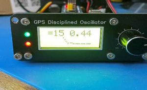
The GPSDO (Pictured right) provides a very good alternative but only puts out 10MHz. A new project I thought! With a quick conversation with ChatGPT I discovered the 74LS390. This seemed like a good option as this Dual 4-bit decade counter had the capability of taking the 10MHz signal from the GPSDO and dividing the signal by 2 to provide a 5MHz square wave output. That used up one half of the chip but producing the 1MHz output was a little trickier. ChatGPT kept saying that I should take the 5MHz output and divide by 5. That would give me a 1MHz out but unfortunately the duty cycle was at 20% whereas I wanted 50%. This was solved by splitting the original 10MHz signal and dividing the second signal by 5 then taking that 2MHz output back into a divide by 2 circuit which then produced an output of 1 MHz with the desired 50% duty cycle.Fantastic, I now have 10MHz, 5MHz, and 1MHz. Everything I ever wanted. Not quite!
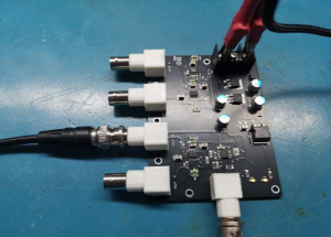
I wanted multiple outputs and had found what I thought was a reasonable solution on ebay. MJTronix produces a 10MHz amplifier with 4 outputs. (Pictured right) Worth a try. And in fact I had used this to distribute the 10MHz and the 1MHz signals from my Quartzlock setup (2 amplifiers). It worked well. I now realised however that I had been putting out signals way over the recommended voltage for quite a while. Fortunately, none of my equipment seems to have come to harm.
So, in fact I needed to provide a 10MHz and 1MHz signal for my two amplifiers, a 5MHz signal for one piece of equipment, and a very low level 10MHz signal for my radios (ic-7610 and ic-9700). This made things much more complicated.
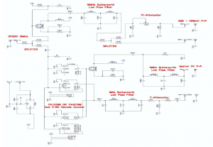
Firstly, simply splitting a signal can produce all sorts of reflections and distortion. I figured that most of the signal paths would require a 50ohm impedance so a simple splitter using three 16.5ohm resistors would fulfil my needs. Unfortunately using this arrangement results in a 6dB attenuation of the signal (halving it). I needed the 10MHz input to be sent to the Divider IC and also as a 10MHz output so I put in a splitter for this purpose. Fortunately the IC seemed to have no problem with one signal being sent to two separate inputs on the chip so I avoided the need for a further splitter there and the attenuation was not a problem. The IC worked fine. The problem occurred down the other leg of the splitter. There wasn’t going to be nearly enough signal so some kind of amplifier was required. I chose a common emitter with a 2N3904 to give me the required voltage gain.
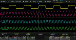
I had looked at the signals from the GPSDO and elsewhere in my circuit as I was building it and I had not envisaged a problem with having square wave outputs, but I was wrong! All the so called square waves were anything but – they were bizarre, and it was probably my fault (although even the GPSDO didn’t give a clean trace). I needed to be in control so I figured that a nicely formed sine wave would be much better and I wouldn’t have to deal with any of those nasty harmonics. How is this achieved? My new favourite circuit, the ‘Butterworth Low Pass Filter’. The maths for calculating the values required is complex but ChatGPT was able to provide them in seconds for a 10MHz, 5MHz, and 1MHz so I was set. This filter removes any signal above the desired frequency thus removing any harmonics. As harmonics are the reason that square waves are that shape then you are left with a perfect sine wave. Fantastic! Much easier to work with.
Having got a nice clean 10MHz sine wave of adequate voltage I then needed to use another splitter. One output went directly to the 4way amplifier and seemed to provide the required input (it is supposed to be 150mV -200mV p-p but actually much greater). With much trial and error this gave the best distributed output I could provide. The other limb of the splitter had to be brought into line as it would be going to my precious radios. I tried using a T-attenuator as I’d had experience with these but soon discovered that taking the signal down to the required low level just resulted in awful distortion. I thought a ?-attenuator might be better, and so it was.
A renowned 23rd century engineer once said (or will say?) “you cannae break the laws of physics” but you can bend them a bit. I wanted to have the output variable so instead of the 270ohm resistor required for the top of the pi I used a 470ohm variable resistor. This allowed me to vary the output from below 200mV to above 400mV – just what I wanted, and the signal remained a clean sine wave. Really getting there now.
The rest of the project was relatively straightforward. I wanted a dedicated 5MHz output of around 3v and to do this I found that again, an amplifier was required. I simply replicated the use of a 2N3904 followed by another Butterworth Low Pass Filter (5MHz this time).
I used another filter for the 1MHz line but this signal needed some attenuation before it was injected into the 4way amplifier. I used a T-attenuator but again took some liberties with the values replacing a 22ohm resistor with a 100ohm. I’m at a loss as to why this worked better (??not 50ohm impedance into the 4way) but it was the only way that I could get a decent waveform on the final output.
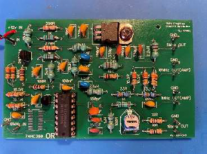
I had built the whole setup on Veroboard (below right) I know, not the best thing for RF frequencies). I wanted to test out things before I went to the wonderful PCBway for a circuit board and actually pay money. It is amazing that you can get 5 circuit board made for under a tenner, and remarkably fast delivery. I made up the board and with very little tweaking got the whole system working. I have now installed the whole thing out of the way in the top corner of my shack.
All in all, this was a worthwhile exercise. I learned a great deal about working with RF frequencies. My maths was adequate in producing a spreadsheet calculator for the attenuators which was invaluable, as was a good deal of advice from ChatGPT. I probably had to question its logic about 50% of the time though, but it always apologised for the errors, so that’s ok.
My test equipment is once again supplied with accurate frequency standard inputs (and is much less likely to blow up now – hopefully).
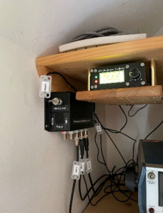
I know there are many better ways to produce the resulting system but although it’s not elegant it works and I’m happy. This was really a chance to play with a soldering iron and keep the brain working. I’m the definitive ‘man with all the gear but no idea’, but by doing, I now have a little more idea.
David G7IBO