

From the Workbench: QRP Labs QCX-Mini
Ian M0IDR and Chris G3YHF have been having fun building this tiny rig. Here’s how they got on….
The QCX-Mini is a miniature version of QRP Labs QCX+ kit. Measuring only 95x63x25mm, it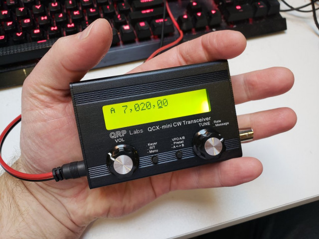 compresses the features of its bigger brother in to a tiny box, giving up to 5w CW on any single band between 80 and 17m.
Photo from http://shop.qrp-labs.com/qcxmini
There are connectors for CAT control and GPS interface as well as the usual power, key, headphones, etc.
Its small size and low power consumption – rated at 58mA on receive with back-light off – means it is ideal to carry in a pocket for /P, SOTA and similar activities.
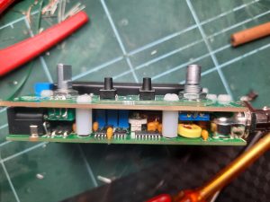
Chris and Ian had both built the bigger QCX Plus (shown in photo below, with QCX-Mini in front) and this was an advantage when starting on the Mini.
Much of the construction process is the same – winding toroids, soldering capacitors and transistors, fitting connectors, LCD, etc. 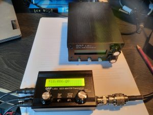
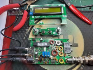
The main difference is that resistors and ICs (except the main microcontroller) are surface mount devices already installed on main PCB. That’s a great help!
There are also display and controls PCBs to be built. These plug in to the main PCB (shown in photo below).
Of course, the PCB is much smaller, and so even greater care needs to be taken to avoid solder bridges. It’s also harder to continuity test some of the components, although following the diagrams in the manual helps identify the connections.
 As with the QCX+, the manual (available on the QRP Labs web site) is comprehensive and contains essential ‘read before you start’ advice. It also has a fault-finding section supported by the Mini’s built-in test equipment and the on-line discussion groups.
The kit comes with an additional small PCB that fits on the main PCB for conversion of the rig to a uSDX SSB SDR transceiver. The parts are not supplied but there is lots of information on-line. Whilst the pcb is supplied by QCX, the use of and small modifications to the main QCX Mini main board are not supported by QCX, so it’s at your own risk.
Chris reports:
I took my time building the rig to make sure my soldering was effective.
When I switched on, the LCD lit up (sigh of relief!), but even after adjusting the contrast potentiometer I couldn’t see any text.
I noticed the display PCB wasn’t sitting flush on the main PCB, and on checking realised that the microcontroller wasn’t fully engaged its socket. That solved the problem!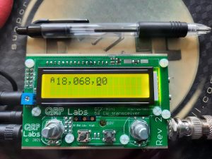
After doing the alignment using the on-board test equipment, I plugged in a QRP wattmeter/dummy load and pressed the key. No response. I checked the continuity across the low-pass filter (LPF) toroids to check that the enamel had burnt off the wire when I soldered them in (this is reported to be the no. 1 cause of no power, and there is lots of advice on how to solder the enamelled wires in the manual). They seemed ok.
So next – following the advice in the manual – I connected a wire to the RF power test point on the PCB and used the other end to check for output from the PA transistor drains. Yes, 5.3 watts.
Then I double checked the RF route from the PA to the LPF and discovered I’d omitted to install a capacitor.
Having soldered this in, I keyed-up and had about 2w out but there seemed to be an intermittent as sometimes the power dropped to 0.
I decided to recheck the PA output and made a fatal mistake – I was doing this in the evening and was quite tired. I managed to short across the transistors with the RF probe. Bang, smell of electrical components burning! End of testing for the day!
 In fact, end of testing until I found a supplier for the transistors and they popped through my letter box.
I managed to extract the old transistors, snipping off the heads and then unsoldering the remaining wires one at a time. But it was a difficult job. I wasn’t able to clear the through-PCB holes and saw I’d damaged the pads on one side of the PCB.
So I had to learn a new skill – cutting the transistor legs to size so I could solder the ends directly to the pads. It worked! Another sigh of relief.
I keyed-up again and had power out but this was still intermittent. I rechecked continuity across the LPF toroid pads and found one that had been OK wasn’t. So perhaps the enamel had burnt off but the wire wasn’t firmly soldered to the PCB? I resoldered, and that solved the problem.
Now to increase the power out.
The QRP Labs web site has a very useful video showing how adjustment of the gaps between the turns on the LPF toroids affects RF out. I widened the gaps on the first toroid until they were evenly spaced and that gave me about 3.2w. Adjusting the second toroid didn’t seem to make any difference, so following the advice I unsoldered one end of the first toroid, removed a turn, and resoldered to the pad – using my new skill!
That gave me about 3.5w. With some adjustment to the wire spacing on the other toroids, I got 4.5w out on a 13.8v supply with key held down.
 Then fit the rig into the neat aluminium enclosure, connect my 17m half-wave and hear ….. only one station. I checked with my K3S and that only received the same station, so it was obviously very poor band conditions!
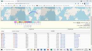
Regardless, I put out CQs on 18.086 – the QRP calling frequency – using the message facility on the rig. No replies, but I was spotted on the Reverse Beacon Network (RBN) by several stations in the USA. So at least I know that my 4 watts was getting across the Pond!
Now I just need to wait for better conditions on 17m for my first QSO!
Definitely a fun kit and I look forward to trying it /P on a hike somewhere.
Ian reports on his build:
I have built all three versions of QCX:
- The original in the silver aluminium enclosure
- The QCX+ in the larger type black enclosure
- The QCX Mini.
So you would expect that the last build would go smoothly I guess!
Well it didn’t get off to a good start as the QCX Mini uses a double sided pcb with surface mount and just starting the build I took a really close look and discovered one surface mount IC was skewed possibly from damage in transit? Anyway a e-mail to QCX and an almost instant reply had the pcb winging its way back.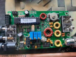
Three days later I had a email reply saying the board was unrepairable and a new one together with a new set of components was on its way. Received 10 or so days later, a quick examination showed no issues and so the build continued.
Out of habit, I check each component is within value with no issues. Takes time but not as much time searching for that duff component in circuit.
As Chris states, the dimensions of the finished cased transceiver are small and therefore the pcb is tightly packed but made easier by all the surface mount pre-assembled.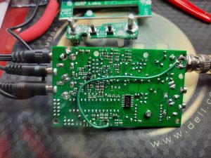
I used a fine chisel tipped Antex soldering iron and found that worked perfectly apart from the power connector pins which fit into rather oversized holes on the pcb. A beefier iron was used with a wider chisel tip for that job.
There are some tricky areas and I found the following worthy of mention:
From the Manual section 3.34 Removing trimmer potentiometer feet. Carefully does it, I used a sharp “Stanley” kife blade to get a clean removal.
Section 3:35 Header pins – needs a lot of heat to fill the through-hole board.
Section 3.36 Bending the rotary encoder pins through 180 degrees. The pins are thin and best to straighten them first and then bend as required. Also they do not “tin” very well.
The various inductors will need to be wound with the supplied enamelled wire and these are not to be rushed. The Manual does state that the turns may need adjusting so do bear that in mind (especially the low pass filter toroids). My build was for 40m version and so the winding turns differ from those on Chris’s 17m version.
Although the soldering process is said to remove the enamel, I did the “gently scrape it” method to get a clean wire to solder. Bear in mind these are through-hole and are more difficulty to unsolder should the need arise.
Everything went together well and the test and setting up went to plan. My 40m unit gives 5.6w of RF at 12v regulated supply.