

From the Workbench – Kanga Rooster QRP Kit Part 1
Kanga? ROOster? Christopher Robin meets ham radio?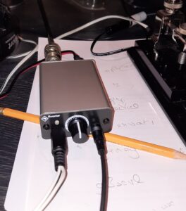
No, just the latest kit from Kanga products.
With Wythall Radio Club’s ‘How low can you go? QRP month looming in January, I thought I’d dig out some of my kit QRP radios.
Back in 2000 I built the Foxx 3 kit from Kanga Products. This 1-watt CW rig was crystal controlled on 7030KHz. It was based on the original 1983 Foxx circuit by George GM3OXX (SK) published in Sprat – the magazine of the G-QRP Club.
Club members have had a lot of fun with this kit. It’s produced contacts with other QRP-ers around Europe.
However, being a direct conversion receiver mine suffered from considerable break-through from the Droitwich Long Wave transmitter about 15 miles away from my QTH.
Now Kanga have produced an updated version of this design called the Rooster.
Like Foxx 3, this is a QRP CW rig for 7030KHz. However, power output has been increased to 2-watts and there is much improved sensitivity and selectivity due to its active audio filter. This is centred on 750 Hz with a 500 Hz bandwidth.
And rather than being mounted in an Altoids tin – the preferred method for Foxx 3 builders – the Rooster is supplied with its own aluminium case.
There are less components and tasks to undertake than when building the Foxx 3 as it uses SMD (surface mount devices) that are pre-installed on the PCB and 20 through-hole parts that the builder needs to solder in place.
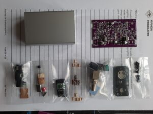 The kit arrived with components neatly packaged in small bags so checking they were all there was a simple task. The 26-page downloadable instructions are in Kanga Products’ usual excellent clear and illustrated format, with instruction for testing each stage after it is completed.
A current limited 12v supply is recommended for testing, but there is probably low risk of damage using a conventional 12v (not 13.8V) supply or battery PROVIDED the location and soldering of components is thoroughly checked after each stage.
I use a magnifying table lamp for checking my soldering, especially for identifying any solder splashes that might result in short circuits.
I spent about 3 hours building and testing the kit. I could have taken less time, but I like to savour the process of construction. In addition, I had a couple of problems (discussed later) that added some time. Kanga suggest that the rig could be built in an hour, eg at a Build-a-thon. It could be with experienced builders, but it would be a rush!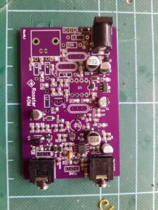
I only had 2 problems. The first was in testing the audio amplifier, where plugging in the headphones and touching a metal screw-driver to particular components should result in a ‘buzz’. It didn’t. There was a weak scratching noise but no buzz.
Using the circuit diagram and my trusty analogue multi-meter, I checked continuity of the audio section, and it was all OK.
The soldering was very straightforward, so I decided just to press on. My faith was rewarded as the next task was to install the side-tone components. When I tested this, it worked perfectly. So clearly, the audio-amp was ok.
The other problem was my error in installing the diode in the neighbouring holes intended for one of the inductors. Just lack of concentration. Unfortunately, I’d trimmed the leads before I realised what I’d done!
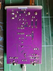 However, I use minimal amounts of solder, so it was easy to remove the diode and clear the holes by pushing one of the trimmed leads into the hole, heating it with the soldering iron, and pulling it through with fine-nosed pliers.
Luckily, the holes the diode should have gone in were not spaced as far apart, so I could fit it and have a tiny bit of the leads poking through the PCB for soldering!
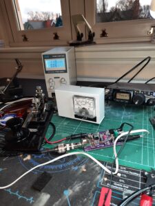
In the final desk test I could hear CW using the short length of coax to the dummy load/watt meter as an antenna. Always a good sign! And the rig produced 2-watts of RF.
So it worked first time – hurrah!
Now let’s get it on the air!
I plugged in my 40-meter dipole and I could hear masses of stations within the receiver’s passband, but unfortunately they were all engaged in an international CW contest! I copied stations in 9A, SP, E7 and YO, so that proved the receiver was working very well. And no sign of Droitwich long wave!
Just to check, I plugged in my Foxx 3 and there it was – a football programme over the top of those CW stations!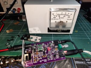
The Rooster definitely has a much better receiver!
It also has masses of audio output but no volume control, so DON’T POWER UP WITH HEADPHONES ON! I need to wear my ‘phones off my ears to reduce the volume.
As the connections between components are not visible on the PCB, I can’t see how to add a small volume potentiometer similar to the one on the Foxx 3. Maybe someone at the Club will advise!
What are the lessons from this build?
Some of the components have solder-points in close association, so if your soldering is rusty – or you’ve never soldered – find or scrounge some Veroboard and components and practice. Check continuity afterwards with a multi-meter set to resistance.
A narrow chisel-type soldering iron tip will work much better than something bigger. It will provide more control where there are components near to each-other.
 A temperature-controlled iron will also help with getting enough heat onto the big lugs of the antenna socket so that they have a good electrical and structural connection.
A dummy load is required. One can be built from resistors, or there are also dummy load/watt meter kits for QRP rigs available.
The fittings that go through the front and back panels (eg DC input, RIT) must be aligned with the edge of the board. I used the panel to make sure they were in the right place, and a bit of tape helped hold them in place until the first lug was soldered.
Overall, this has been a very enjoyable little kit to build. It’s priced at £37.99 plus P and P and given it includes a metal case I think that’s a reasonable cost.
It’s a good first step for anyone starting out with construction, and could then lead to the QRP Labs QCX-mini one band, fully featured CW rig (not crystal controlled!) currently at £44 plus £16 for the case plus P and P.
Once I’ve had a play with the Rooster on 7030 I’ll post an update on how it performs.
Works and sounds really well having just had a QSO with Chris on 7030 this morning .. at least 579 given .. really nice tone too
1